1. Set job units and import a known test file
Begin with a test job in millimetres. Use your build's vector import or open command to load the DXF. The official V5 manual documents vector import plus job-unit settings; menu placement and importer behaviour can differ in other versions.
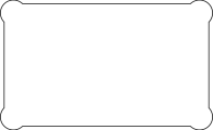
If the importer offers a units choice, select millimetres. If it does not, inspect the result rather than assuming it is correct. The sample below uses a 50 × 30 mm nominal pocket, all four minimal dogbones and a 6.35 mm cutter.
2. Check outer extent, walls and relief radius
The nominal pocket is 50 × 30 mm. Its relief-inclusive outer extent is 51.860 × 31.860 mm, and each circular relief has radius 3.175 mm. Compare the imported geometry's width and height with the outer extent, not with the nominal straight-wall dimensions.
A factor of 25.4 suggests an inch/mm conversion error. Stop and correct the units or re-import. If a proven unit error must be corrected by scaling, scale the complete contour uniformly and recheck both dimensions and relief radius. Do not stretch one axis or scale relief to make a joint looser.
SVG is an alternative when your build imports it successfully: this site's SVG has millimetre width/height and a matching viewBox. Measure it too. The symmetric rectangular coupon cannot prove that an importer has not mirrored an asymmetric part.
3. Check closure before creating a toolpath
The DXF expresses one continuous closed contour as separate LINE and ARC entities. A particular importer may create several editable objects. Inspect endpoints and any open-vector warnings; join only coincident pieces as your version requires.
There should be one relief contour, not a rectangle with overlapping cutter circles. Do not add a second automatic dogbone treatment. If an SVG has a guides layer, remove that reference outline and cutter circles before machining.
4. Choose Pocket or a compensated Inside contour
For a recessed slot, create a Pocket operation to remove the interior. For a through opening where the interior will be released, an Inside contour can be appropriate with suitable workholding. A contour on the vector centreline places the cutter across the intended boundary.
Set the end mill to the same physical diameter used here: 6.35 mm is 0.25 in. Let CAM calculate compensation once; do not pre-offset the finished contour by the cutter radius and then compensate it again.
Inspect stock thickness, Z zero, cutting depth, the side of the boundary being cut and the relief regions in simulation. Cutter engagement changes around corners; depth per pass, feeds and workholding depend on the material and machine, not a generic relief recipe.
5. Cut and measure a coupon before the final part
Verify the operation above the stock before cutting a small coupon. Measure the actual flat-wall opening and test the mating tab. Record material thickness, cutter, measured dimensions and whether the corners or straight faces contact first.
If the file measures correctly in software but the cut does not, check tool selection, effective cutter diameter, runout, deflection and machine calibration. Increasing corner relief does not correct an undersized slot along its whole length.
The generator's edge-length separation check prevents overlapping reliefs; it is not a tolerance or machining guarantee. The downloadable contours have been checked as files, but no Carbide Create build, machine import or physical cut is certified by this page.